

Rockler CNC Demonstration #2 – Spoil Boards for CNC Shark
 January 6, 2018
Material List: 24” x 48” x ¾” sheet MDF
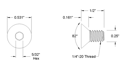
36 – ¼ ” x 20 x ½” flat head machine screws
36 – ¼ ” x 20 oval nuts
Tool List: ¼” end mill up spiral
½” standard countersink bit
1 ½” diameter Freud TM1465
Prep work: Cut MDF in to 3 – 16” x 24” pieces
 In VCarve : Create Design
- Start new file
- 24” x 16” x 0.75”
- Discuss Z Zero and XY Datum
- “DRAW RECTANGLE”
- Anchor lower left, X=0.5, Y=1.5
- Radius corners, 1/8”
- Set W=2.625 H=13, Create
- Next create temporary rectangles to help locate holes
- Leave anchor point same
- Change to square corners
- W=13/16, Y=3, CREATE
- Repeat for top right corner
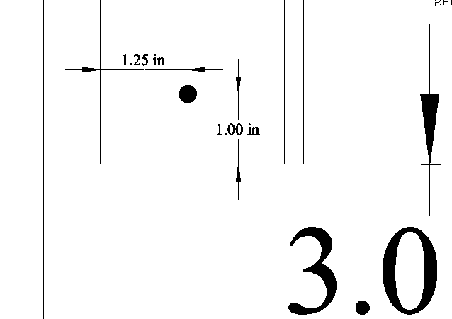
- “DRAW CIRCLE”
- Draw 3 circles at the inside corner of each temporary rectangle
- One with each of these D=0.6, D=0.5, D=0.25
- Delete both rectangles
Note: For today’s Demo we premade 16 of the 18 required spoil boards to save time and minimize the amount of noise created while cutting the MDF parts. We will just run the last 2 spoil boards to allow us to install all 18 needed to complete this project.
- “ARRAY COPY”
- Select all then select Array Copy
- Rows=1, Columns=8 (see Note)
- Gap = ¼” plus 1/32”
- Click Copy
- DONE ready to make TOOL PATHS
In VCarve : Create TOOL PATHS
- Set properties
- Datum to lower left
- “Pocket Tool” path for 0.6”D circle
- Select all 0.6”D circles
- Select pocket toolpath
- Cut depth 0.5
- Select ¼” EM, Edit with pass depth 5/32, Feed rate 75
- Name as Clearance Hole and calculate
- “Drill Toolpath” for 0.25”D circle
- Select all 0.25”D circles
- Select Drilling Toolpath
- Cut depth 0.78
- Select ¼” EM
- Name as Drill Hole and calculate
- “Profile Toolpath” for all 8 spoil boards
- Select all 8 board profiles
- Select Profile Toolpath
- Cut depth 0.78
- Select ¼” EM, Edit with pass depth 5/32, Feed rate 60
- Add tabs ½ x 1/8 thick
- Name as Profile 8 boards and calculate
- Save all 3 toolpaths above to one file on USB
- Add tool description to file name
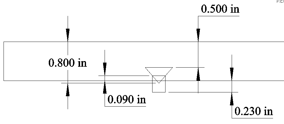
- “Drill Toolpath” for 0.5”D circle
- Select all 0.5”D circles
- Select Drilling Toolpath
- Cut depth 0.8
- Select ½” 90 degree V bit
- Name as Countersink Hole and calculate
- Save above Tool Path to USB
- Add tool description to file name
- Save ENTIRE project file
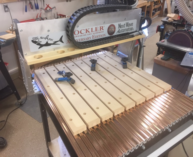
Set up wood to be cut
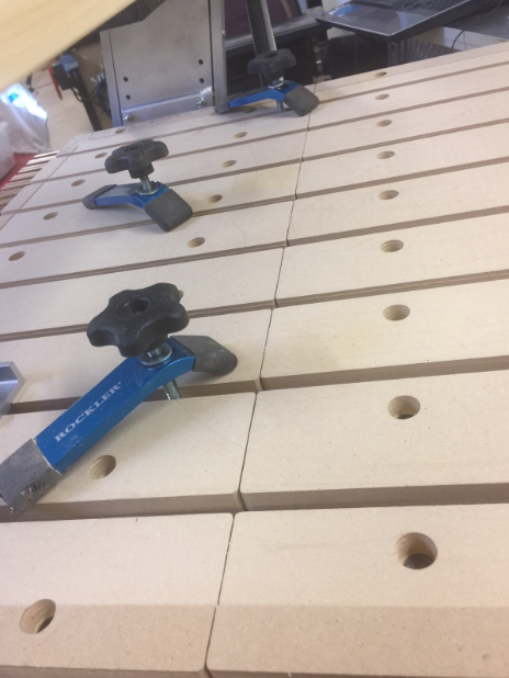
- Make sure properly secured – show broken bit and hold down clamps
- JOG create 0,0,0
- Demonstrate Z set up
 Run file for ¼ End Mill
- Run file for Counter sink bit
Assemble spoil boards and tighten hardware
Next we will create tool paths to resurface the spoil board to assure they are flat and then remove radius corners and excess material in the X+ and Y+ direction.
In VCarve :
- Start new file
- 24” x 24” x 0.75”
- “DRAW RECTANGLE”
- Anchor lower left, X=0, Y=0
- Square corners
- Set W=24 H=24, Create
- “DRAW POLYLINE”
- Top left to top right to bottom right, end
- Lower left up 45 degrees for ½”
- “MIRROR COPY”
- Select lower left polyline
- Select Mirror Copy
- Click square Flip about center
- Click square Create a mirrored copy
- Click Flip Vertical
- Reselect lower and upper left polyline
- Click Flip Horizontal
- Close mirror copy
 In VCarve : Create TOOL PATHS
- Set properties
- Datum to lower left
- When running this toolpath, set 0,0 to dimensions shown at right.
Caution! You must first confirm that using these dimensions will not cause over travel of CNC carriage.
- “Pocket Tool”
- Select 24 x 24 Rectangle
- Select pocket toolpath
- Cut depth 1/64”
- Select 1-1/2” EM, Feed rate 100
- If tool not in DB, copy and create
- Name as Resurface and calculate
- “Profile Toolpath”
- Select Polyline that goes from top left to bottom right
- Select Profile Toolpath
- Cut depth 1/64
- Select 1-1/2” EM, Feed rate 100
- Click on
- Name as Top and Right, calculate
- “Profile Toolpath”
- Select all 4 small Polylines in the corners
- Select Profile Toolpath
- Cut depth 1/64
- Select 1-1/2” EM, Feed rate 100
- Click on
- Name as Clear Corners, calculate
- Save all 3 toolpaths above to one file on USB
- Add tool description 1-1-5EM to file name
- Run this file
QUESTIONS?
Front View Back View 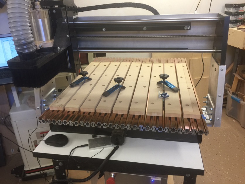
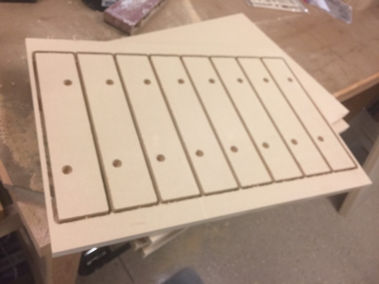
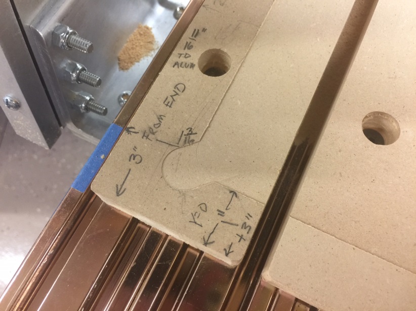
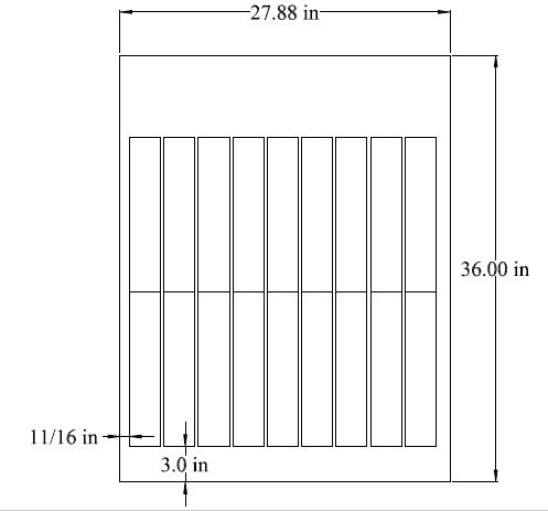
 Corner Cutout 8 Spoil boards on 16 x 24 MDF
There will be a seam down the middle with 2 rows of 9
10 comments
What modifications would you suggest to make this work for the Next Wave CNC Shark II/HD500?
Sean, I don’t work for Nextwave/Shark but all models I am aware of use the same deck aluminum extrusions some the attachment method would be the same for all models. Is the HD 500 the 16 x 36 bed? If so you could use the current design and just put 3-12” pieces in the aluminum extrusion slot, front to back. Or if your up to it you could modify it to 18” and use 2 pieces front to back. Is thi what you were looking for?
I really like this design and used it on the HD510 at work. I will soon possess a HD520. Any thought on the following?
1) Have you modified or changed your spoilboard design?
2) For my HD520, I’m planning on having the same 18 pieces just twice as long.
Mark, I no longer have a Shark CNC and don’t know the difference between a 510 and 520 so I am sorry I can’t be much help.
I would think as long as the shark has the same aluminum extruded bed design this design will work with slight modifications to length.
You can call me at 714-791-1658 if you want to discuss this further.
Hi Mark, I just got the 510 and was looking for a Vcarve file to create a spoil board. I was wondering if you or TJ had one I could use?
TJ sorry to hear you no longer have a Shark. The 510 bed is 28″ X 36″ with a 25″-25″ cut area. The 520 is a 25″-50″ cut area otherwise I think all three of the 500 series are the same.
Thank you for posting all the information here very helpful.
-tim-
I understand setting the drill 2nd drill hole and profile boards beyond the depth of the project so it cuts all the way through. But I’m not understanding why the counter sink is a .8 depth. Won’t this make the whole hole large and eliminate the small hole?
Hi Annie. As I recall when I used TJs design it left just enough of a hole at the bottom for the screw and made the original hole larger at the top so the head of the screw fits.
Mark this is correct. The depth of cut using the countersink bit is critical. Either of you can call me at 714-791-1658 if you still need help.
Hi everyone…I’m new to the cnc playground. I just got the HD520 and was wondering if anyone had a spoilboard for it? Would be nice if it was ruled. If not I’m going to try to create one myself. If I get one completed I will post it here.
No one has one that I know of. If you make it please post.