

200
Text on 3D Component Surfaces
Tools used in this Demo – 1/8” and ¼” Ball Nose
Create Design
- Start new file – Fill out job set up
- Single sided
- 11 W x 3.5H x 0.75 Thick
- Choose data point preferences
- Click OK
- Go to Clip Art Tab
- Go to “Domes” folder
- Select “Dish_Dome_30”, double click will center it
- Go to “3D Tabs” folder
- Select “Rectangular_0.5”, double click will center it
- Select “Rectangular_0.25” and drag one to line up with left of the work piece
- Go to drawing tab to resize all 3D Objects
- Select the Dome
- Select “Set Selected Object Size”
- Enter 9” in either width or height and check box to link XY
- Click Apply and Close
- Select the Rectangular 0.5” Object
- Select “Set Selected Object Size”
- Enter 8” W x 3” H
- Click Apply and Close
- Select the Rectangular 0.25 Object
- Select “Set Selected Object Size”
- Enter 1” W x 0.75” H
- Click Apply and Close
- Adjust height and relationship between all 3D Objects
- Go to Modeling Tab
- Select the Dome by double clicking to bring up the properties box
- Change Height to 0.5”
- Change Base Height to 1/16”
- Check “Add”
- Click Close
- Select the Rectangular Object by double clicking to bring up the properties box
- Change Height to 3/16”
- Check “Add”
- Click Close
- Locate first 3D tab, got to properties and change to 3/8” thick, locate on left side then copy to the right side
- Create Text Box
- Go to Modeling Tab
- Select Rectangular _0.5
- In 3D Model Tools, select “Create Vector Boundary”
- Go to Drawing Tab
- Select the boundary box created in step above
- Select “Draw Text in Vector Box”
- Enter “Rockler”
- Chose Text “Gulim”
- Check Bold
- Check Normal Margin
- Vertical stretch set to “Stretch Characters”
- Click “Close”
- Select “Edit text spacing” and add spaces between letters to allow for an 1/4” EM tool
- IMPORTANT Select Box and create an offset of 1/8”, delete original, TJ to explain this
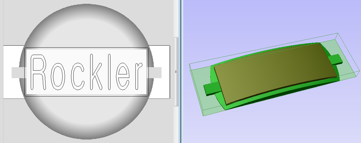
- You should have something like the above picture and are now ready to make TOOL PATHS
Create TOOL PATHS
 Set properties
- Tool clearance to 1”
- Set datum to lower left
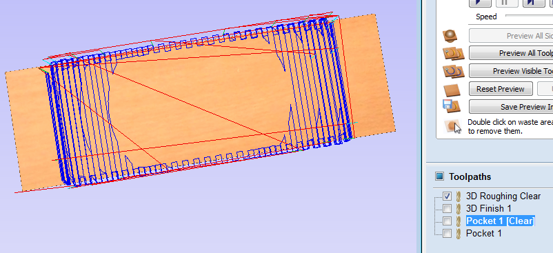
- Use 3D Roughing tool path
- Select the border box
- Select 3D Roughing tool path
- Select 1/4” Ball Nose and enter depths and speeds for your machine
- Check “Selected Vectors”
- Enter a boundary offset of 0.25”
- Enter a machine allowance of 1/32”
- Select Z Level, Raster X, Profile None
- Change Name to Roughing Clear
- Click Calculate
- Use 3D Finishing tool path
- Select the border box
- Select 3D Finishing tool path
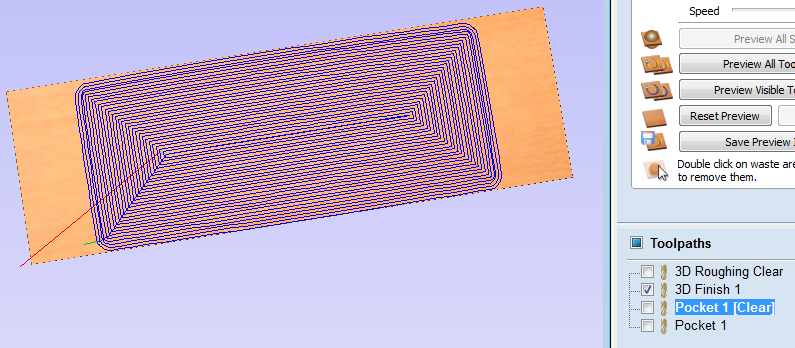 Select 1/4” Ball Nose and enter depths and speeds for your machine (to make a nice smooth finish on the top of the letters, either use a small step over number or sand smooth when done)
- Check “Selected Vectors”
- Enter a boundary offset of 0.125”
- Select Offset Conventional
- Change Name to Finish Surface
- Click Calculate
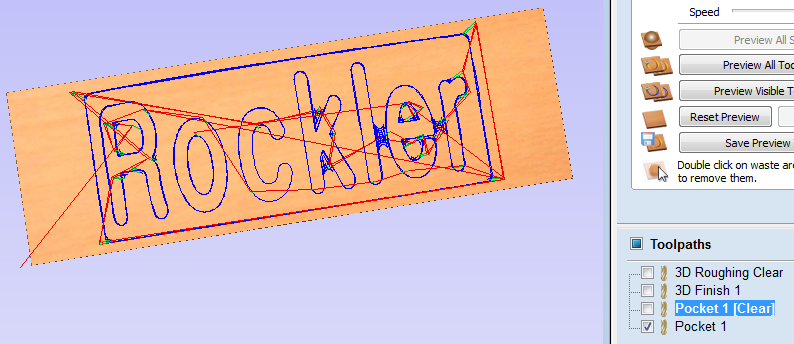
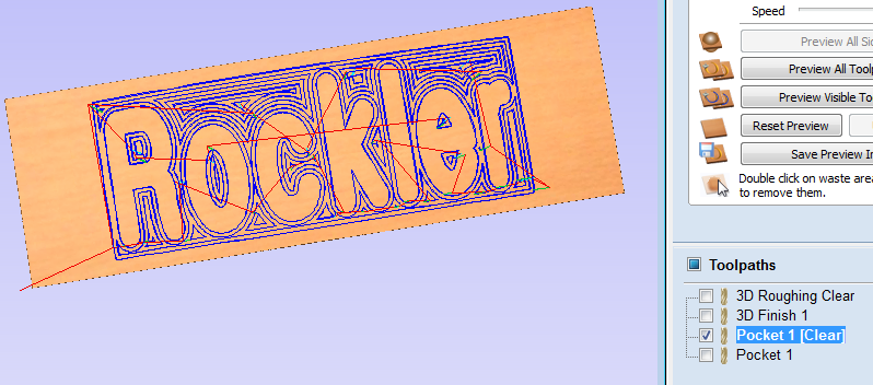 Use the “Pocket” tool path
- Select both the text and border box
- Select Pocket tool path
- Set start depth to 0”
- Set cut depth to 3/16”
- Check “show advanced toolpath options”
- Select 1/8” Ball Nose and enter depths and speeds for your machine
- Check “Use Larger Area Clearance Tool”
- Select 1/4” Ball Nose and enter depth and speeds for your machine
- Select offset / conventional
- VERY IMPORTANT Click box for “Project toolpath onto 3D model”
- Change name to Pocket Text
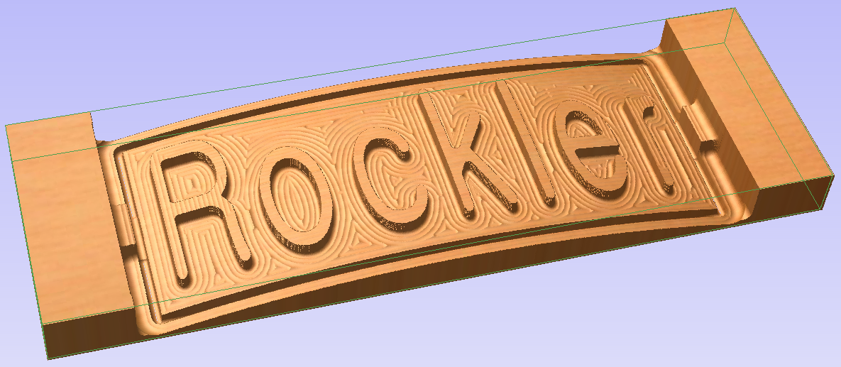
- Click Calculate
- You will notice 2 toolpaths were made, one for each tool size
 Save above Tool Paths to USB drive
- Add tool description to file name, for pendant machines make first 5 characters meaningful
- Save ENTIRE project file
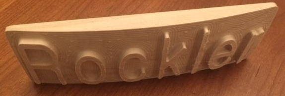
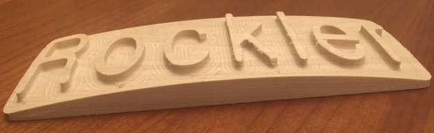
- DONE – ready to cut
Set up wood to be cut
- Make sure properly secured
- JOG create 0,0,0
- Run file for 3D Rough (pre run before Demo)
- Run file for 3D Finish (pre run before Demo)
- Run file for Text Pocket Clear
- Run file for Text Pocket
Question?
Ideas for next Demo…