

Where to get SketchUp
There are several versions of SketchUp
SketchUp Free Online
This is the most current version of SketchUp and is free to use but you must have internet access.
Sketchup Installer
There are several versions of the installer all available at https://www.sketchup.com/download/all. You must create an account to be able to download these files. I will be using SketchUp Make 2017 for this demo.
- SketchUp Pro 2019
- Not Free Can install for 30 day demo
- SketchUp Viewer 2019
- Free only used for Viewing SketchUp Files
- SketchUp Pro 2018
- Not Free Can install for 30 day demo
- SketchUp Pro 2017
- Not Free Can install for 30 day demo
- SketchUp Make 2017
- Free for local install – This is the version we will be using in this demo.
Sketchup Learning
A good site for learning SketchUp
https://www.sketchup.com/learn
Searching YouTube is also great site for training video and questions
Sketchup Warehouse
Best location to find a large community of SketchUp Models.
https://3dwarehouse.sketchup.com
SketchUp 101
The website https://getmethod.com/blog/sketchup-101 was used as a basis for this class.
Toolbars
I like using the following
- Getting Started- Go To: View>Toolbars>Getting Started
- Large Tool Set- Go To: View>Toolbars>Large Tool Set
- Styles- Go To: View>Toolbars>Styles
- Layers- Go To: View>Toolbars>Layers
- Standards- Go To: View>Toolbars>Standards
- Views- Go To: View>Toolbars>Views
Large Buttons
This makes toolbars easier to read- Go To: View>Toolbars>Large Buttons
Axis
Each axis has a solid line on one side of the origin and a dotted line on the other, the axis lines orientation is:
- Solid Blue line extends up from the origin
- Dotted Blue line extends down from the origin
- Solid Red line extends East from the origin
- Dotted Red line extends West from the origin
- Solid Green line extends North from the origin
- Dotted Green line extends South from the origin
Shortcut keys
When using the drop-down menus at the top, pay attention to commands that have a letter to the right, those are shortcut keys that you can use from the keyboard.
Modeling Basics
- Always use the axis to draw everything. Use the arrow keys on your keyboard to lock directions. The up and down arrows will lock the blue axis. The right arrow key locks the red axis and the left arrow key locks the green axis.
- Make use of Groups and Components.
- Creating a Group is simply a way to combine several objects together, into one ‘piece.’ For instance you can create a window that is comprised of an upper and lower sash as well as glass. You can than make a group out of the ‘pieces’ which than makes it easier to edit and move it within the model. Groups can be copied and edited.
- A Component is a type of group that when copied and repeated, if one Component is edited all of the other Components will change as well. This is useful for windows that are used repeatedly and is very helpful when creating units for multi-family buildings. For instance, you could create a Double Hung window unit and place it 40 times in your model, if you than edit one Component to be a casement window, the other 39 update as well. Components can also be mirrored using the Flip command. The mirrored Components retain their definitions, and are updated whenever an un-mirrored version is updated.
- To create a Group or Component, select all the objects that you want included, right-click the mouse and select Make Component or Make Group, it’s also found under the Edit drop-down menu at the top of the screen.
- Groups and components can be edited by double clicking them.
- When drawing shapes and lines, you can key in actual dimensions, look at the bottom right of the screen for the dimensions dialogue box.
- The basics of modeling are to draw shapes, select from the toolbars or Go to: Draw drop-down menu. Then you manipulate the shapes by the Push/Pull tool and various others selected from the toolbars or the drop-down menus.
- Linear Arrays create multiple copies of entities or geometries (use it for posts at an on-center spacing, siding, beams, etc.) To create an array:
- Select the entity to be copied
- Select the Move tool, press and release the CTRL (PC) or Option (MAC) key, the Move tool icon should now have a ‘+’ sign.
- Click on the selected entities to copy and move your mouse to copy, easiest if you key in dimension spacing, click destination point.
- Type a multiplier to create additional copies, i.e. typing 4x will create a total of 5 copies, the original entity and the 4 copies.
- There are several other ways to create linear arrays, as well as radial arrays, search online or use the SketchUp help forums.
- Use Layers, they make it easier to control the visibility with-in the model and group similar ‘pieces.’ From with-in the Layers dialogue box select the ‘+’ sign to create a new layer and name it as you wish. From this box you can also select which layer is ‘current’ and all modeling is currently being placed in.
- Use the Tape Measure tool to create drawing guidelines, it can be accessed either from the toolbar button, Go to: Tools>Tape Measure, or by pressing ‘T’ on the keyboard. After a while your model may have a lot of guidelines, you can delete them by, Go to: Edit>Delete Guides.
- You can import files to use as site plan or floor plan references, Go to: File>Import and select the type of file to import. You can scale the imported file by using the measuring tool to measure a known dimension and scale accordingly using the Scale tool.
- The Follow Me tool is a great time saver for creating moldings. The tool will take any multi-sided plane (e.g., a section through a piece of molding) and extrude it along a line or curve. Draw the shape you want to extrude. Then select the Follow Me tool, click on the shape and drag it along the path you want it to follow.
- A lot of time can be saved by using models/components others have created. Go to: File>3D Warehouse>Get Models and search for what you want. Once imported into your model, they can be edited as you like. You can also share models/components you create, Go to: File>3D Warehouse>Share Model.
- To apply a material, Go to: File>Window>Materials, the Select button should be highlighted, from this dialogue box numerous standard materials can be applied by selecting a material and then using the paint bucket to select the model pieces to receive the material. Be sure to select the Shaded With Texture button in the Styles toolbar or you won’t see the material.
- Once a material is placed it can be edited, Go to: File>Window>Materials, the Edit button should be highlighted, from here you can edit the color, scale, and opacity of the material. You can also use your own images to create materials or images from a manufacturer’s website.
- After placing materials, you can edit them in the model by right-clicking on the material and selecting Texture>Position (if you right-click again there are some additional options). Four colored ‘pin’ tools appear that allow you to modify the position and scale of the material. The two most commonly used are the Green ‘pin’ which allows scaling and rotating of the material and Red ‘pin’ which allows moving of the material. Using these ‘pins’ allows scaling of the material to match a known dimension and placing the material at a ‘starting’ point.
Import Sketchup files to Aspire
Import SketchUp 3d Models
Available only in Aspire and is just like importing any other STL file. As most members do not have Aspire it will not be covered in this demonstration.
Import SketchUp Vectors
To start importing SketchUp Vectors you can do one of the following
- <File>-<Import…>-<Import Vectors…>
- <CTRL>+I
- Click on

The Open File dialog will appear and you then select the SketchUp File.
Once you select the file and open it the following dialog will appear.
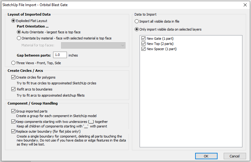
I rarely change any settings except for “Data to Import”. This is where you can select what layers you import.
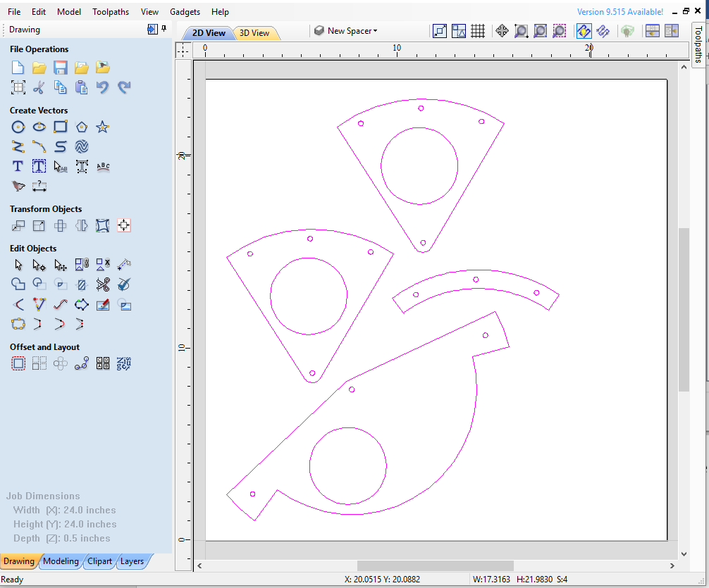
Once the file is imported you can create toolpaths from the imported vectors.